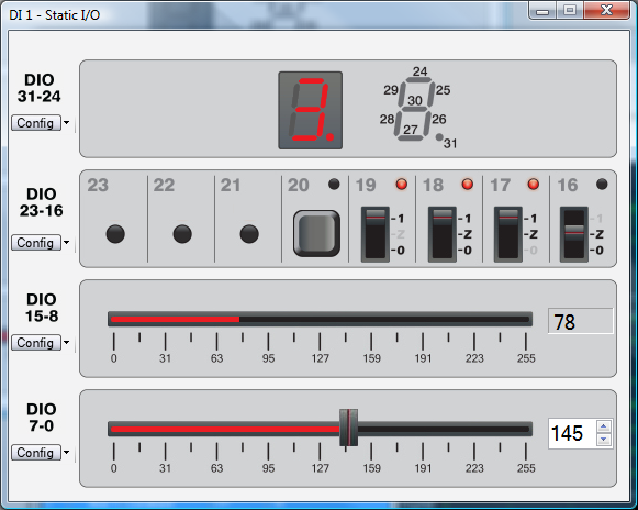
The SIO instrument allows easy configuration of input and output devices on the digital lines. It is called "static" because the value from the digital lines corresponds directly to the values generated or read by the input and output devices. Once a signal value is set, it remains in that state until a new value is set.
The SIO controls the digital signals of the device, which are managed in groups of eight: 31-24, 23-16, 15-8, and 7-0.
For each group of signals, a device can be assigned. See Define Input Output Devices Types for specific device types.
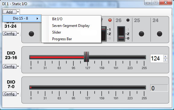
In the instrument form, devices are placed in a vertical stack.
It is possible to Remove/Add groups of eight lines. See Remove/Add Lines Group.
See SIO Configuration for information about instrument configurations.
For each line group, a device can be assigned the following types:
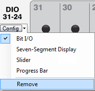
The device type is selected using the group's Config button.
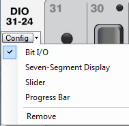
By selecting one of the four types, the device type is changed. The current type is checked.
The Remove option removes the group from the display.
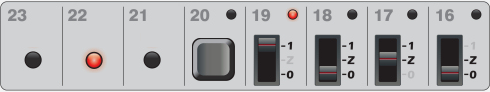
This device type assigns a specific bit device for each of the eight digital lines in the group. Bit devices include:
The selection is done by right clicking on the area correspoding to the specific digital line.
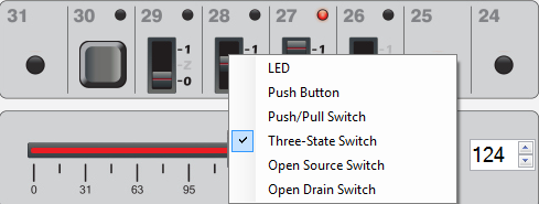
The current bit device is checked. The bit device type changes when you select another option.
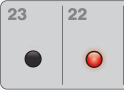
This is an input device, indicating the digital line's state.
Input behavior:
If the line is driven high, the LED is lit.
If the line is driven low, the LED is unlit.
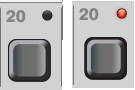
This is both an input and output device, implementing a push button with LED indicator. The button has two states: pressed and released.
The button can be pressed by clicking on it. As long as the mouse button is pressed, the button stays pressed. Also, after selecting the button with the mouse, you can press it using the Enter key or Spacebar. While either of those is pressed, the button stays pressed.
Output behavior:
While the button is pressed, the digital line is driven high. While the button is not pressed, the digital line is driven low.
Input behavior:
If the line is driven high, the LED is lit.
If the line is driven low, the LED is unlit.
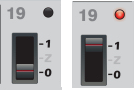
This is both an input and output device, implementing a push/pull switch with LED indicator.
The switch has two positions: 0 and 1.
The switch position can be set in the following ways:
Output behavior:
When the switch is set to 1, the line is driven high. When the switch is set to 0, the line is driven low.
Input behavior:
If the line is driven high, the LED is lit.
If the line is driven low, the LED is unlit.
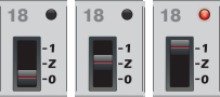
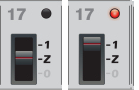
This is both an output and input device, implementing a three-state switch with LED indicator.
The switch has three positions: 0, Z, and 1.
The switch position can be set in the following ways:
Output behavior:
When the switch is set to 1, the line is driven high.
When the switch is set to Z, the line is driven high Z.
When the switch is set to 0, the line is driven low.
Input behavior:
If the line is driven high, the LED is lit.
If the line is driven low, the LED is unlit.
This is both an output and input device, implementing an open source switch with LED indicator.
The switch has two positions: Z and 1.
The switch position can be set in the following ways:
Output behavior:
When the switch is set to 1, the line is driven high.
When the switch is set to Z, the line is driven high Z
Input behavior:
If the line is driven high, the LED is lit.
If the line is driven low, the LED is unlit.
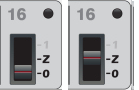
This is both an output and input device, implementing an open drain switch with LED indicator.
The switch has two positions: Z and 0.
The switch position can be set in the following ways:
Output behavior:
When the switch is set to Z, the line is driven high Z
When the switch is set to 0, the line is driven low.
Input behavior:
If the line is driven high, the LED is lit.
If the line is driven low, the LED is unlit.
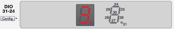
This device type implements an input device for displaying a seven-segment digit and a decimal point. Each of the eight digital lines corresponds to one of the segments or the decimal point, according to the legend displayed on the right of the digits display.
Input behavior:
If the line is driven high, the segment or decimal point is lit.
If the line is driven low, the segment or decimal point is unlit.
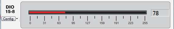
This type implements an input device used in displaying values between 0 and 255 as a progress bar and value display.
The digital values of the eight input lines are converted into a value between 0 and 255. The digital lines' binary values are used as bits in a binary representation where the highest-number digital line is the most significant bit (MSB). .
The value is displayed as a red progress line and as a numeral in the read-only field on the right.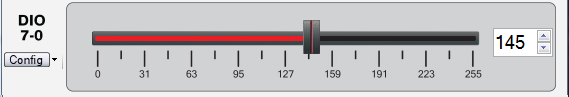
This device implements both an input and output device.
The output device configures the eight digital lines according either to the value of the slider caret's position or the value entered in the direct value field .
The device looks similar to the progress bar.
Output behavior:
The device lets you specify the output value as a number between 0 and 255 by moving the slider caret or by entering a number in the direct value field (by typing or using the up and down controls). As the caret is moved, the corresponding value is filled in the direct value field. As the value in the direct value field is modified, the slider caret position is updated.
The value is used as an eight-bit binary representation where the highest-number digital line is the most significant bit (MSB) and each digital line gets the value of the corresponding bit.
Input behavior:
The digital values of the eight input lines are converted into a value between 0 and 255. The digital lines' binary values are used as bits in a binary representation where the highest-number digital line is the MSB.
The value is displayed as a red progress line and as a numeral in the field on the right.
It is possible to Remove/Add one or more groups of eight digital lines. Note that the groups with larger line numbers are always displayed above the ones with smaller numbers (e.g., it is not possible to place DIO 23-16 above DIO 31-24).
If a group of lines that was implementing an output device (slider, for ex) is removed, then these lines are no further used by SDIO. So, Patterns instrument can use them.
To remove a group:
As devices are removed or added, the main form's height is adjusted.
In the default SIO configuration, all the line groups are configured as bit I/O LED bit device types. When the instrument is opened, it uses the most recent configuration.
Unlike other instruments, it does not allow the selection of other configurations.