The Arbitrary Waveform Generator generates electronic waveforms. The waveforms can be either repetitive or single-shot. Different triggering sources can be used: internal (from other devices) or external.
The resulting waveforms can be input into a device being tested and analyzed with the Oscilloscope as they progress through the device. This is useful for confirming the proper operation of the device or pinpointing a fault in the device.
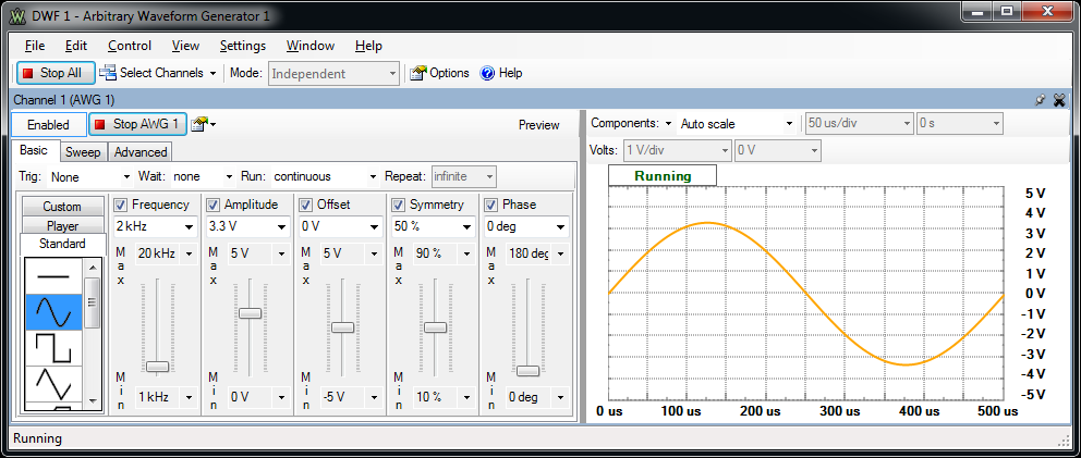
The main window has three areas: the toolbar at the top, the configuration form(s) on the left side, and the signal preview plot(s) on the right side.
Run All / Stop All button: starts or stops the selected signal generators.
Select Channels list: selects the channel(s) to be controlled. For every channel you select, a configuration form and a signal preview plot are displayed.
Synchronization Mode: The waveform generator channel synchronization modes are available when more than one channel is selected.
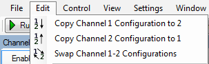
Change: copies or swaps the channel configurations. They can also be changed using the Edit menu, as shown below.
For every channel you select, a configuration form is displayed.
For more information, see Basic Configuration Mode, Sweep Configuration Mode and Advanced Configuration Mode.
For every channel you select, a signal preview plot is displayed.
The Preview button displays or hides the signal preview plot.
A horizontal left-button mouse drag on the plot changes the start position and a right-button mouse drag changes the horizontal domain of the preview.
A vertical left-button mouse drag on the left/right side changes the modulator/voltage position and a right-button mouse drag changes the vertical range of the preview.
The actual output might differ from the preview, especially at high frequencies.
Enable button: enables or disable the output.
Run/Stop button: starts/stops the signal generation for the selected channel. The waveform generator channel can be started individually. When both waveform generator channels are enabled, and at least one of them has no trigger selected, the Run All button starts signal generation for both channels synchronously.
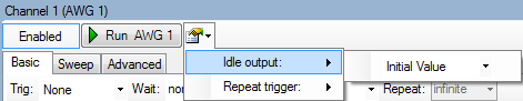
The channel options lets you select:
The Basic tab selects the basic configuration mode for a simple signal configuration. The signal type can be Standard, Custom or Player.
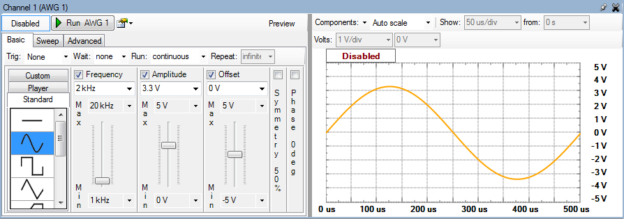
Standard mode is selected from the list on the left side of the Basic configuration form.
Signal icons represent the standard signal types: Sine, Rectangle, Triangle, Ramp-Up, Ramp-Down, Noise, Triangle-Square, and Sine-Power.
For the Noise signal, the Frequency slider represents the sample frequency, and the Symmetry slider is disabled.
The Sine-Power signal is a sine signal where the power attribute is 0. For higher power attributes, the waveform tends to have square shape. The function for the power attribute is the following:
if (power > 0) = Sine(x) ( 100 / (100-power) )
if (power < 0) = Sine(x) ( (100+power) / 100 )
Frequency, Amplitude, Offset, Symmetry, and Phase sliders let you easily modify signal values between the maximum and minimum limits. These limits can be adjusted using the combo boxes above and below the sliders.
Trigger, Wait, Run, and Repeat settings let you generate burst signals. See States for more information.
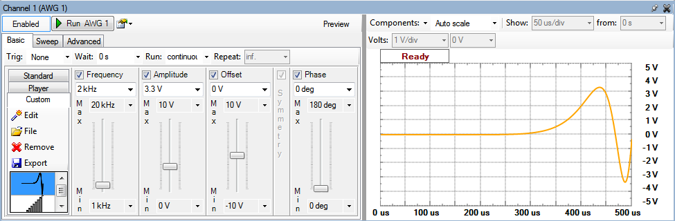
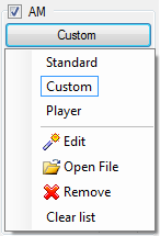
Custom mode is selected from the list on the left side of the Basic configuration form.
Edit button lets you edit a signal. See Editor for more information.
File button lets you load a signal. See Import file for more information.
Remove button lets you remove a signal.
Save button lets you save a signal to a .CSV file.
Frequency, Amplitude, Offset, and Phase sliders let you easily modify signal values between the maximum and minimum limits. These limits can be adjusted using the combo boxes above and below the sliders.
Trigger, Wait, Run, and Repeat settings let you generate burst signals. See States for more information.
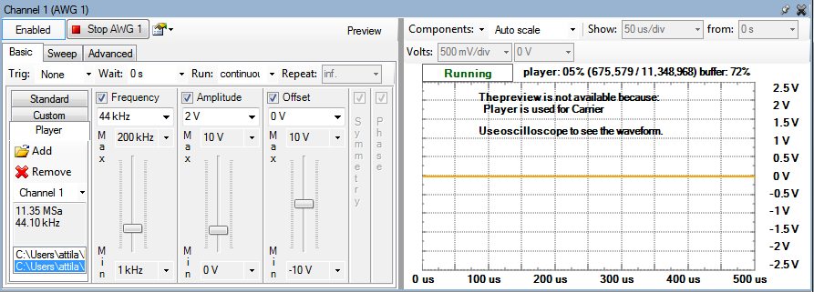
Player: mode is selected from the list on the left side of the Basic configuration form. This mode lets you play back files.
Add button lets you add signal files. The supported file formats are Coma Separated Values (*.csv) and Waveform audio file (*.wav).
Remove button lets you remove a selected signal.
Channel selector lets you select a channel to output the signal.
Frequency, Amplitude, and Offset sliders let you easily modify signal values between the maximum and minimum limits. These limits can be adjusted using the combo boxes above and below the sliders.
The Frequency slider represents the sample frequency in Player mode. The maximum frequency is limited by the buffer size.
When the PC or the USB is busy the playback might be jumpy. In this case try stopping the other
running instruments or reduce the playback frequency.
The supported WAV files formats are: PCM and IEEE float, mono and stereo, in a single data chunk.
The player can also be used in advanced mode for carrier, amplitude or frequency modulation.
If the device buffer is emptied, the player will lose samples and a warning message will pop up. If this problem occurs, stop other instruments or quit applications that burden the computer or reduce the player frequency.
Sweep tab selects the sweep configuration for easy setup of sweep and damp signals.
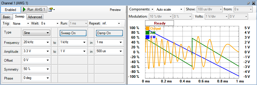
The Sweep On/Off and Damp On/Off buttons enable or disable these modes.
In sweep mode, the signal frequency changes linearly from the first value to the second in the specified time.
In damp mode, the signal amplitude changes linearly from the first level to the second in the specified time.
Frequency, Amplitude, Offset, Symmetry, and Phase sliders let you easily modify signal values. These settings can be adjusted using the combo boxes next to the sliders.
Trigger, Wait, Run, and Repeat settings let you generate burst signals. See States for more information.
The repetition time (Repeat setting) reflects the largest time period between the sweep and damp periods. When both sweep and damp are disabled, the repetition time uses the signal period (the opposite of the frequency). The actual runtime is displayed to the right of the Run field.
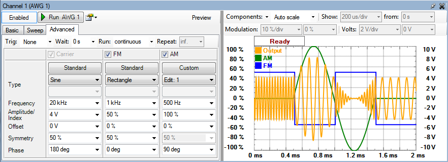
The Advanced tab selects the advanced configuration mode for setting complex configurations.
Trigger, Wait, Run, and Repeat settings let you generate burst signals. See States for more information.
Carrier, FM, and AM signals are configured in separate columns.
Signal mode can be Standard, Custom or Player.
Configurations consist of:
See Generator States and Idle output for more information.
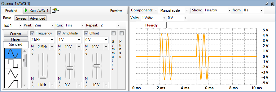
Using the (Trigger), Wait, Run and Repeat settings, burst signals can be generated.
The following screenshot shows a burst signal.
The Editor lets you easily create arbitrary signal shapes as well as custom carrier signals and modulators.
To launch the Editor from the Basic or Advanced configuration form, select the Custom signal option and then select Edit.
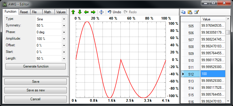
Function generation has the following parameters:
Constant tab let you reset the entire buffer to a constant level.
File tab lets you import data from a file and place it in the buffer at a specified starting position and for a specified length. See Import File.
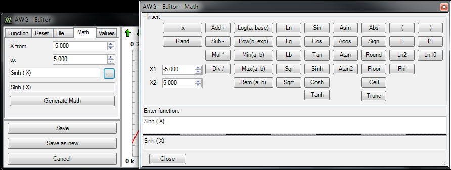
Math tab lets you generate signals from mathematic functions.
Value tab lets you fill the buffer with values by typing. Copy, paste, insert and multiple editing are also supported.
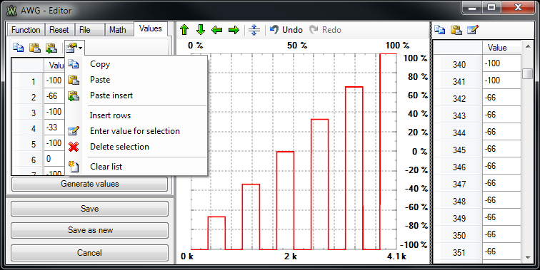
Arrow icons lets you move buffer data horizontally and vertically. You can also do this by dragging the sides of the plot area. Vertical levels that exceed the limits (±100%) are truncated when saving.
Stretch vertically will normalize the values between -100% and +100%.
Undo / Redo lets you undo/redo the last changes in the buffer.
Plot area lets you draw the signal with the mouse. When the mouse cursor leaves the plot on one side, it continues the drawing from the other side. This helps you create continuous curves.
Value can be edited in the data tab on the right side. Copy, paste and multiple editing is supported.
Save button stores the changes and closes the Editor.
Save as new button stores the data buffer as a new entry and keeps the original buffer.
Cancel button closes the Editor without saving any changes.
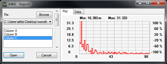
To import a data file into the Basic or Advanced configuration form, select Custom and then select File.
The Import dialog opens with either the last opened file, or if this is your first time importing a file, with an Import Open dialog that lets you specify a file.
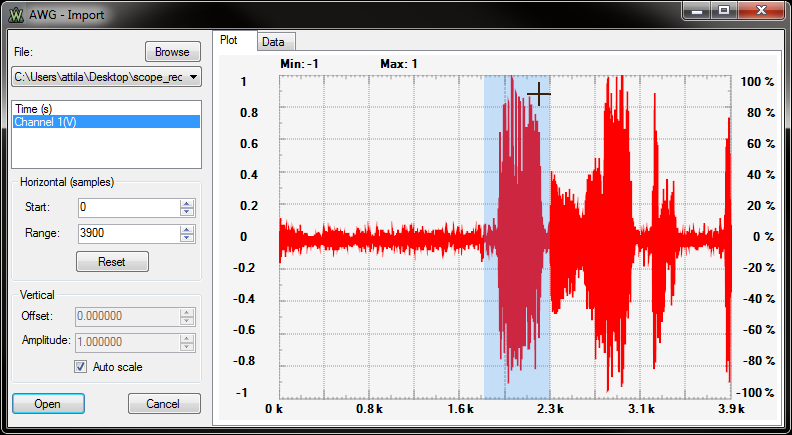
Browse button opens a dialog box where you can select a different file to load.
File combo box lists previously opened files you can load.
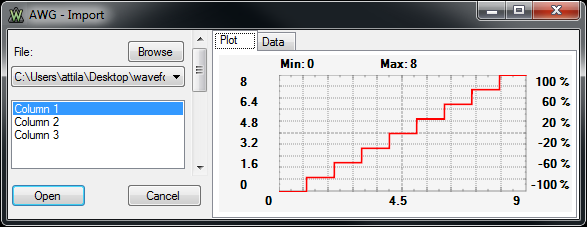
If the file contains several columns of data, select the one to use from the list below the File combo box.
Horizontal (samples) controls let you specify the samples to load from the file.
Start and Range fields specify the samples’ start index and range.
Reset button resets the Start and Range values to include all available samples.
Plot area shows the selected data range. This can be also selected by dragging the mouse on the Plot area and clicking the highlighted region. Dragging on the top or bottom side of the plot area with the left mouse button changes the start position. Dragging with the right button changes the selected range.
Vertical controls let you adjust the sample vertically using the Offset and Amplitude parameters. Dragging the left or right sides of the Plot area with the left mouse button changes the offset. Dragging with the right mouse button changes the amplitude.
Auto Scale lets you automatically stretch the data vertically.
Open button loads the specified sample into the Plot area.
Cancel button closes the dialog without saving any changes made.
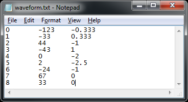
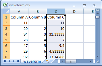
Supported files are tab delimited or comma separated values files (as shown below). These file types can be created with applications like Notepad, Excel, etc.
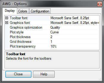
The options can be accessed from the settings menu.
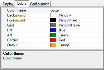
The Colors tab lets you select the color options for background, foreground, grid, AM and FM modulators, carrier, and output.
Changing the Color Theme loads a default set of colors.
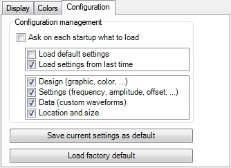
Ask on each startup what to load lets you select whether the default or last configuration is loaded at start-up, as well as which items to configure.
Save current settings as default saves the settings you have selected as default.
Load factory default restores the default settings.