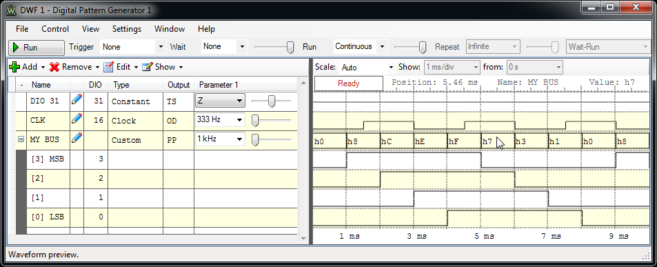
Digital Pattern Generator
The Digital Pattern Generator (Patterns) lets you definine the output on the digital lines, using standard types or user-defined types.
When a line is used by the Static I/O (SIO) as an output element (Slider, Button, or Switch), this has priority
over the signal configuration in Patterns.
1. Menu Strip
1.1. File Menu
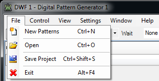
- New Patterns: opens a new Patterns instrument.
- Open: opens a Patterns project from file.
- Save Project: saves the Patterns project to file.
- Exit: closes the Patterns window.
1.2. Control Menu
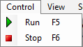
- Run: starts the generator.
- Stop: stops the generator.
1.3. View Menu
1.4. Settings Menu
See Settings Menu.
1.5. Window Menu
See Window Menu.
1.6. Help Menu
See Help Menu.
2. Toolbar

Run/Stop button: starts/stops the signal generation.
Trigger, Wait, Run, and Repeat settings let you generate burst signals. See States for more information.
3. Signals Definition Grid
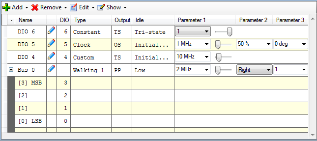
The Signals Definition Grid lets you customize the display of the signals that you are interested in.
The signals and buses can be reordered or signals removed/added to a bus
with right mouse button drag. See the operations on Lists
for more information .
3.1. Add
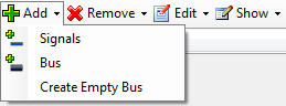
It is possible to add signals, define and add a bus, create an empty bus, or
create a bus with the selected elements.
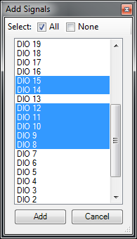
One or more signals can be selected and added at a time.
The Add Bus menu opens a bus property editor
and after configuring the bus, adds it to the grid.
3.2. Remove
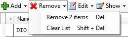
It is possible to remove the selected items or clear the entire list.
3.3. Edit
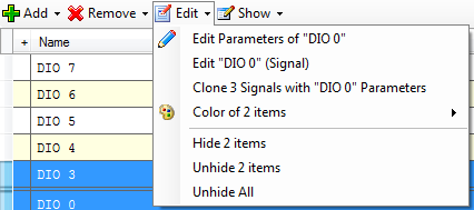
Under the Edit menu the following operations can be performed:
- Edit Parameters: Opens the parameter editor for the
last selected item.
- Edit Properties: Opens the properties editor for the last
selected item.
- Clone Parameters: Clone the selected items with the last
selected item parameters (type, output, frequency, etc.). Only items of the
same type, signal or bus, will be cloned.
- Color: Opens the color dialog for background or
foreground and sets this color for the selected items.
- Hide: Hides selected items.
- Unhide: Unhides selected items.
- Unhide all: Unhides all hidden items.
3.4. Show
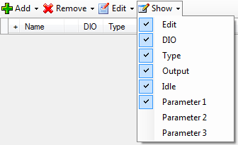
Under the Show menu the visibility of grid columns can be selected. The grid
columns are the following:
- Height: The row height can be changed in the first
column. When more rows are selected and one of them is resized, the height
of all selected rows will be changed.
- Expand/Collapse: Each bus can be individually
expanded or collapsed. Clicking on the column header expands or
collapses all the busses.
- Edit: Clicking on the edit icon of the signal or bus
line opens the parameter editor.
- Type: Selects the type (constant, clock, random,
custom, etc.) of signal or bus.
- Output: By clicking on this column, a combo box lets
you select the desired output for the corresponding signal or bus.
- Idle: Selects the output for
the idle state, when the
generator is not running (Config, Armed, Done, Stopped or Wait state).
- Parameter #: Adjusts the parameter values for the
selected signal or bus. The values can be adjusted between the minimum
and maximum values selected in the parameter editor.
3.5. Context Menu
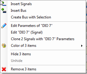
The grid context menu opens on mouse right click. This contains similar buttons as the grid toolbar's Add, Remove and Edit menus.
The difference is that instead of signal or bus addition, the insert
operation will be performed
above the last selected row.
4. Property Editor
The property editor can be opened for the selected signal or bus on the
grid toolbar's edit menu, under the context menu or by mouse middle-click on
the row.
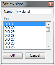
In the signal property editor, the name can be specified and the
device pin changed.
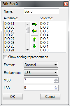
In the bus property editor, the following options can be configured:
- Name: Edit the displayed name of the bus.
- Available: Shows the available (unused) signals.
- Selected: Shows the selected bus signals. The
signals can be added or removed with the left-right arrow-buttons or
mouse drag and drop. The order of the bus signals can be changed with
up/down arrow-buttons or with mouse drag and drop.
- Show analog representation: Select to display the
analog representation of the bus values.
- Format: Selects the values format of the bus. This can be
one of the following:
- Binary values are displayed with "b" leading
character.
- Decimal
- Hexadecimal values are displayed with "h" leading
character.
- Vector values are displayed with "v" leading
character. Vector value is the raw binary value without index.
- Endianness: Selects between little and big endian,
least significant bit (LSB) first or most significant bit (MSB) first.
- LSB/MSB: Selects the values for first and last
indices, LSB and MSB. The index values can be set so that the index
remains within the -32 and +31 range.
5. Parameter Editor
The parameter editor can be opened for the selected signal or bus under the
grid toolbar's edit menu, under the context menu, or by mouse double-click on
the row. This window will hide automatically, but by selecting the Lock link it
will become a docking window.
5.1. Parameters
The type, output, and idle parameters have dedicated columns in the signal
definition grid. For the Value, Frequency, Duty, Phase, and Initial Value
parameters, a minimum and maximum value can be specified and linearly changed
using the track bar.
The Idle parameter lets you select the signal or bus output while not
running.
The output type determines the output behavior of the signals and buses. For OD and OS signals, use external pull-up or pull-down resistors. The output types are:
- PP - Push Pull: The allowed values are 0 and 1.
- OD - Open Drain: The allowed values are 0 and Z. The bus value is computed by treating Z as 1.
- OS - Open Source: The allowed values are Z and 1. The bus value is computed by treating Z as
0.
- TS - Three State: The allowed values are 0, 1, and
Z. The bus values that contain only 0s and 1s are shown as normal
numbers. A question
mark is displayed for values that contain Z in at least one of the bus signals.
The possible parameters for different types are the following:
- Constant: By default, a newly added signal or bus
is a constant with value Z. According the output type parameter 0, 1,
and Z values can be selected.
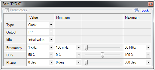
- Clock: The parameters used to define a clock
signal:
- Output lets you select between PP, OS, and OD.
- Frequency lets you specify the clock frequency
expressed in Hz. The maximum clock frequency is half of the digital
base frequency.
- Duty lets you adjust the duty factor between 0%
and 100%.
- Phase lets you adjust the clock phase between 0
and 360 degrees.
- Random: The random values are generated on the
device. It is not possible to show a preview for this type. To see the
output, use the Analyzer instrument or generate custom/random data.
- Output lets you select between PP, OS, OD, and
TS. In TS output, the chances for output levels are the following: Z 50%, 0-low 25% and 1-high 25%.
- Frequency lets you specify the random output
update frequency.
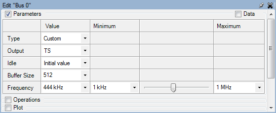
- Custom:
- Output lets you select between PP, OS, OD, and
TS. In TS mode the available device buffer size is half as much as in other modes.
- Buffer Size lets you specify the used device
sample buffer size. On generation the buffer is repeated while
running.
- Frequency lets you specify the sample update
frequency.
- Constant Number: Using this type, the bus values
will be generated as a constant value.
- Output lets you select between PP, OS and OD.
- Value lets you specify the bus constant bus
value.
- Binary/Gray/Johnson Counter: Using these types, the bus
values will be generated as binary/Gray/Johnson counter values.
- Output lets you select between PP, OS, and OD.
- Frequency lets you specify the bus value change
rate. For example, at 1kHz the binary counter will increment every
1ms.
- Initial Value lets you select the counter start
value for binary and Gray counters. A Johnson counter will always
start with 0 value.
- Walking 0/1: Using these types, the bus values will be generated as
a train of 0 or 1 bits walking left or right.
- Output lets you select between PP, OS, and OD.
- Frequency lets you specify the bit shift rate.
- Direction lets you select left or right shift
direction.
- Length lets you specify the train length of the
0 or 1 bits.
For custom type prefill, import, export, data, and plot group are displayed. These
help define the custom data samples.
5.2. Custom Prefill
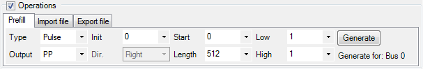
The prefill can be generated on the selected rows from a Start
index and with the specified Length. With TS output type the
prefill can be generated as PP, OD, or OS types. The following
prefill types are supported:
- Constant: Prefill with 0, 1, or Z value.
- Pulse: Generates pulses with the selected initial
value, and low and high times.
- Random: Generates random values with the specified
initialization value. When the Init is random, the generated
result will be different every time. With a specific Init value,
the result will be the same. TS random can be generated with a result
probability of: Z = 50%, 0 = 25% and 1 = 25%.
- Constant Number: Prefills the buffer with a
constant bus Value.
- Binary/Gray/Johnson Counter: Generates incremental
counter values. For binary and Gray counters, the initial Value can
be specified.
- Shift/Rotate Value: These prefill operations apply
a shift or rotate Value. Every value is computed by shifting or
shift-rotating the previous value bitwise to the specified left or right
Direction.
5.3. Custom Import
The supported import file types are Comma Separated Values and Tab
Delimited Text files.
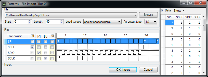
- File: The combo box stores the recently opened files
and a new file can be selected with the Browse button.
- Start: Specifies the first sample position to be imported.
- Length: Specifies the number of samples to be
imported. This can be set up to the minimum between the number of samples
in the file or the device buffer size.
- Load values: Selects between loading the value one-by-one for each signal from a bus or entire bus values.
- As output type: For TS types, selects between PP, OD,
OS, or TS import mode. In PP mode, Z values will be imported as 0; in OD
mode, 1 will be imported as Z; in OS mode 0 will be imported as Z.
- Plot:
- File column: Shows the file column names.
- Rows: The file data plot.
- [#] columns: The checkboxes let you select for which
signal which file data column to
import.
- Data: The checkbox in the top-right corner shows the read file data in a grid.
- Show lets you select the file data lines to
display.
5.4. Custom Export
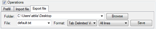
The export function lets you export the custom data in Comma Separated Value and
Tab Delimited Values with current system and with US regional options. By
default All lines are saved. For buses, the Only selected lines
option saves the selected lines.
5.5. Custom Plot
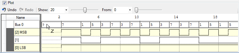
The custom plot shows the custom data buffer and allows mouse editing. By
keeping the mouse over the waveform area, the cursor indicates a 0, 1, or Z value,
depending on the vertical position in the row and on the allowed values. By
pressing a mouse button, the value of the corresponding element in the buffer
will be changed to the value shown by the cursor. By dragging the mouse,
multiple buffer positions can be edited with the same value (all positions
between the start and the end of the operation). On a bus waveform, all the signals will be changed to
the 0, ,1 or Z
value. Dragging with the left mouse button and changing the vertical position
can change the entered value. Dragging with the right mouse button keeps the initial value.
The Undo and Redo buttons let you reverting the last 16 changes.
The Show lets you select a smaller number of samples than the
buffer size starting
From the specified value.
5.6. Custom Data
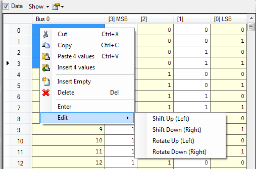
For custom type the data samples can be edited on the right side after
selecting the Data checkbox.
Under the Show button the displayed signals can
be selected.
The context menu can be opened with a right mouse click. This allows the
following:
- Cut: The selected values are placed into clipboard and the data is deleted from
the grid.
- Copy: The selected values are placed into
the clipboard.
- Paste: The values that are in the clipboard are
inserted starting from the current position, overwriting the initial values on those positions in the grid. The current position is the
top left cell of the current selection.
- Insert: The values from the clipboard are
inserted starting from the current position, the top left cell of the
current selection. Values after the current point are shifted down in
the buffer (towards the end of the buffer).
- Insert Empty: Empty cells (containing neutral
values Z or 0) corresponding to the current selection size are inserted
in the current position. Values after the current point are shifted down
in the buffer (towards the end of the buffer).
- Shift Up (Left): For every selected signal, its
selected values are shifted up, towards the beginning of the buffer,
with the number of positions you indicate.
- Shift Down (Right): For every selected signal, its
selected values are shifted down, towards the end of the buffer, with
the number of positions you indicate.
- Rotate Up (Left): For every selected signal, its
selected values are rotated up, towards the beginning of the buffer,
with the number of positions you indicate.
- Rotate Down (Right): For every selected signal, its
selected values are rotated down, towards the end of the buffer, with
the number of positions you indicate.
6. Options
The options can be accessed from the Settings menu.
6.1. Display Options
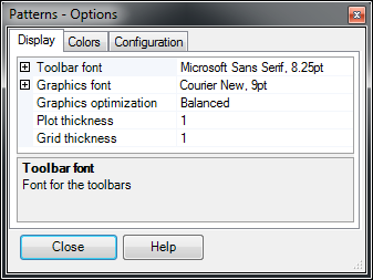
- Toolbar font: selects the font and size for the toolbar.
- Graphics font: selects the font and size for other text.
- Graphics optimization: adjusts the balance between quality and speed.
- Plot thickness: sets the thickness of the sample plot, expressed as points.
- Grid thickness: sets the thickness of the grid lines, expressed as points.
6.2. Colors Options
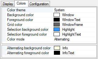
The Colors tab lets you select the color options for background,
foreground, grid, selection background and foreground.
Three color modes are supported:
- Uniform: In this mode all the rows have the same
background and foreground color.
- Alternating: In this mode the rows have alternating
background and/or foreground color. The alternating color can be
configured below.
- Custom: This mode lets you specify unique
background and/or foreground color for each bus and signal.
Changing the Color Theme loads a default set of colors.
6.3.
Configuration Options
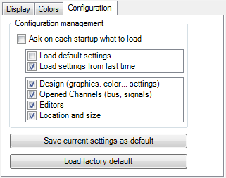
Ask on each startup what to load: lets you select whether the default or last configuration is loaded at start-up, as well as which items
to configure.
Save current settings as default: saves the settings you have selected
as default.
Load factory default: restores the default settings.