Starting with the Analog Explorer
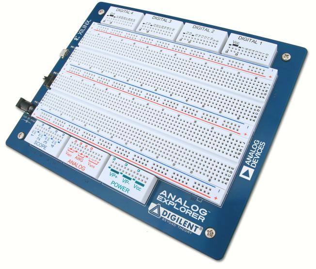
1. Hardware
To set up the Analog Explorer:
- First install Digilent WaveForms software on your PC. See Installer Details for more information.
- Connect a 12V 60W power supply to the Analog Explorer board.
- Connect the Analog Explorer to your PC using a USB cable.
- The Ready LED will light when the Output Enable switch is ON and the WaveForms application is connected to the board.
2. WaveForms Software
See Installer Details for information on installing WaveForms.
See WaveForms for information on using the
software.
3. Troubleshooting
In case you receive the error message "Communication with device failed":
- Remove all the attached components and wires from the Analog
Explorer.
- Verify that the USB cable is attached correctly.
- Reconnect WaveForms to the Analog Explorer and, without opening any
instruments, verify that the WaveForms system monitor is receiving voltage and current levels.
The Analog Explorer's system monitor displays the voltage, current, and
temperature. In the main window, click the Explorer
button to show this information.

When no instrument is running, the device consumes about ? watts (? A). Depending on usage, consumption can increase
subject to the following limitations:
- At ? A consumption or voltage bellow ?V, the Analog Explorer displays a warning.
- At ? A or bellow ?V, the Analog Explorer stops and displays an error message. You can disable/enable this feature on the main window. Click the Device button, click Settings, then click Overcurrent Protection.
- At ? A, the Analog Explorer stops, in order to prevent damage.
- See Power Supplies for information
regarding limitation of these.
4. Oscilloscope
The Analog Explorer has four differential oscilloscope input channels.
Specifications:
- The input bandwidth is ? MHz.
- The positive and negative inputs
have an impedance to ground of 1 MOhm in parallel with 10 pF.
- The ADC is 14 bits and 100 MSps.
- The absolute maximum input voltage is
±? V.
- The buffer can be up to 32 kS (default is 16 kS) on 4 channels.
- The input gain is adjustable, resolution from 12 uV to 30 mV,
resulting peak to peak input from 200mV to 50V.
5. Arbitrary Waveform Generator
The Analog Explorer is equipped with two Arbitrary Waveform Generators channels.
Verify the voltage on the Waveform Generator channels before connecting it to a circuit.
Specifications:
- The output bandwidth is ? MHz.
- The output current is ? mA.
- The DAC is 14 bits and 100 MSps.
- The maximum output is 30 Vp-p, between -15 V and +15 V.
- The resolution
is 2 mV for amplitudes above 3 V, and 500 uV for amplitudes of 3
V and lower.
- When a channel is closed or disabled, the output is not
in high impedance but outputs 0 volt.
- The carrier buffer can be up to
32 kS
(default is 16 kS). The AM and FM buffer can be up to 8 kS (default is 4 kS) on two channels.
- The stereo audio jack outputs the AWG signals. AWG 1 outputs on left channel and AWG 2 on the right channel.
The positive and negative power supplies can be used as slow voltage or current waveform generators.
6. Power Supplies and
Multimeter
The Analog Explorer has three power supplies.
NOTE: When the power supplies need to drive high capacitive loads, start the supply before connecting the load.
Specifications:
- The positive power supply has a range of 0 to 15 V and 0 to 2 A current limit.
- The negative power supply has a range of 0 to -15 V and 0 to 2 A current limit.
- The digital power supply has a range of 0 to 5 V and 0 to 2 A current limit.
- The reference voltage supplies can provide only limited current, up to 10 mA.
The disabled reference voltage output is not in high impedance but should be close to zero volts.
- The voltmeter differential input range is +/-30 V, resolution of 1 mV, limited to +/-15 V relative to GND.
Measures DC, AC RMS and True RMS.
- The ammeter input range is +/-2.5 A, resolution 10 uA, limited to +/-15 V relative to GND.
. Measures DC, AC RMS and True RMS.
- Power measurement can also be
performed by propper wireing the voltmeter and ammeter channels.
- The
measurement are updated at 2 Hz and are computed on 2048 conversion
samples.
- DC result is the average, Sum[ xi ^ 2 ] / N
- True RMS is the
Sqrt( Sum[ xi ^ 2 ] / N ), where xi are the conversion samples
- AC
RMS is the Sqrt( Sum[ (xi - DC) ^ 2 ] / N ), where xi are the
conversion samples
7. Digital I/O
The Analog Explorer has 16 digital I/O (DIO 0-15) and 3 trigger I/O pins.
Specifications:
- The digital pins are supplied at 3.3 V.
- The pins have a 12 mA drive strength.
- The pins have a 220 Ohm series thermistor and diodes to GND and 3.3V, having protection between -? V and +? V.
- The pins can output push-pull (PP), open-drain (OD), open-source (OS), and three-state (TS) signals. For OD and OS signals, use external pull-up or pull-down resistors.
- The generator/analyzer frequency is 100 MHz.
- The Logic Analyzer buffer can be up to 64 kS (default is 8 kS).
- The Pattern Generator custom buffer can be up to 64 kS (default is 8 kS).
- The Logic Analyzer can work on an external clock, up to 100 MHz.