Designing and Simulating a CMOS inverter using Electric VLSI (first pass)
This tutorial shows how to run Electric VLSI Design System
to design and simulate a CMOS inverter using ON Semiconductor's C5 standard technology.
ON Semiconductor C5 is a 0.5 \(\mu\)m CMOS process optimized for 5V mixed-signal applications, with 3 metal layers and poly-to-poly capacitors.
The drawn transistor length is 0.6 \(\mu\)m.
The focus is on how to quickly setup and and run the EDA tools (Electric, LTspice, ngspice).
For learning how to use the tools an excellent resource of tutorials and examples is Jake's Baker web page
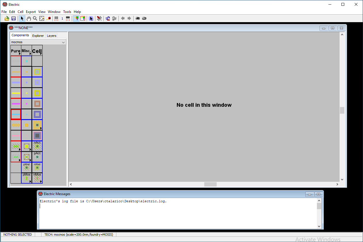
1. start electric from the CLI
$ electric
or double click on its icon
 |
 |
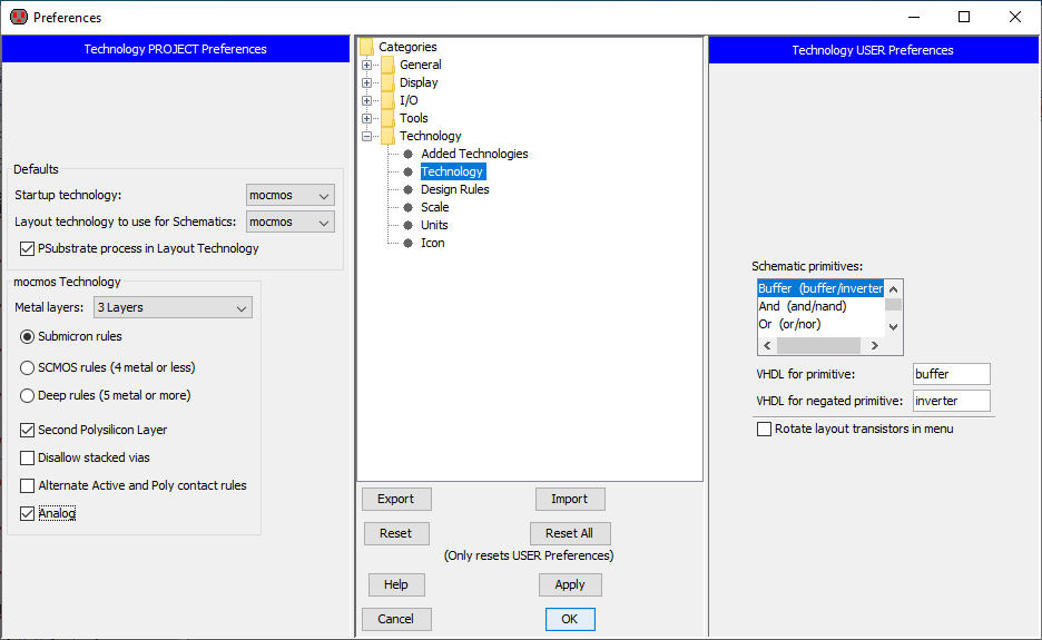
2. Setup Electric's technology preferences
The C5 CMOS process has 3 metal layers and 2 poly layers and can be manufactured through MOSIS using the scalable (L=2\(\lambda\)) CMOS submicron design rules.
select File -> Preferences -> Categories -> Technology -> Technology
set the following options:Startup technology: mocmos
Layout technology to use for schematic: mocmos
PSubstrate process in Layout Technology
mocmos Technology
Metal Layers: 3 Layers
Submicron rules
Second Polysilicon Layer
Analog
 |
select File -> Preferences –> Technology -> Scale
set the following options:mocmos scale 300nm
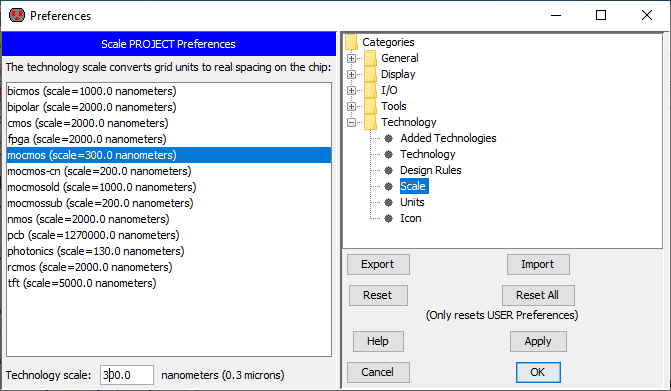 |
NOTE: the selection File –> Preferences has a shortcut icon
 |
3. create a new library
File –> New Library
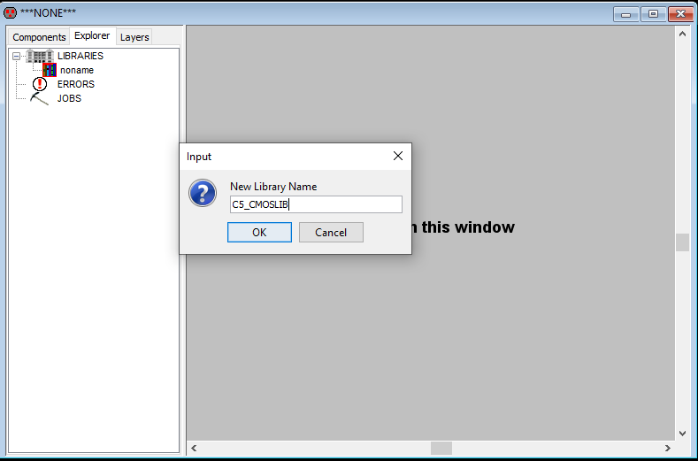 |
click OK and save the library in your favorite location (example: //VBOXSVR/talarico/ngs406/Electric)
The name of the file corresponding to the library is C5_CMOSLIB.jelib
4. create a new schematic cell
Cell –> New Cell
Library: C5_CMOSLIB
Name: C5_inverter_VTC
View: schematic
5. edit the schematic
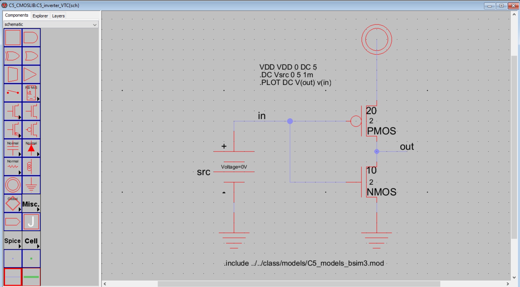 |
Power, ground, pmos and nmos transistors are just one click away on the palette of the components
wires are also just one click away on the palette of the components (they are called arcs)
to place a wire first left click on the component's port you want to start from, then hold the right button and drag
the DC voltage source is available inside the Spice repository (Spice > DCvoltage)
spice directives can be inserted through the Misc repository (Misc > Spice code)
to label a wire double click on it and change the default name
to change the default width and length of a transistor double click on it and edit its sizes
to change the default name of the DC voltage source double click on it and enter the desired name
note: the name shown in the schematic is padded with the correct spice prefix (i.e. the effective name of the device is Vsrc)to add to pmos and nmos transistors their model names use Tools > Simulation (SPICE) > Set Spice Model
to change any of the properties of the various schematic objects (for example font size, or location) select the object and use
Edit > Properties > Object Properties | Qto check the correctness of the schematic use Tools > DRC > Check Hierarchically | F5
6. common commands
Windows > Toggle Grid | Ctrl G
Edit > Copy | Ctrl + C
Edit > Paste | Ctrl + V
Edit > Erase Selected | Delete
Edit > Rotate | J
Edit > Undo | U
Edit > Mirror > (Up/Down) | Y
Edit > Mirror > (Left/Right) | X
Edit > Duplicate | C
Edit > Move selected –> use updown and leftright arrow key or drag
Edit > Move selected > Align to Grid | Alt A
Edit > Properties > Object Properties | Q
Window > Full Window | F
Windows > Zoom Out | Ctrl+0
Windows > Zoom In | Ctrl+7
Toos > DRC > Check Hiererchically | F5
To customize/change the key bindings use File > Preferences > General > Key Bindings
7. simulate the circuit with LTspice
go to File > Preferences > Tools > Spice/CDL and set the following preferences
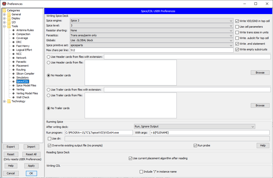 |
NOTE
Run Program: C:\PROGRA~1\LTC\LTspiceXVII\XVIIx64.exe
With args: -i ${FILENAME}
C:\PROGRA~1 is the same as C:\Program Files
C:\PROGRA~2 is the same as C:\Program Files(x86)
run the simulation: Tools > Simulation (Spice) > Write Spice Deck
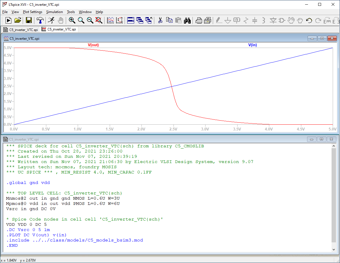 |
Unfortunately, electric is not able to read the latest LTspice raw format, so it's impossible to plot the simulation output directly within electric (unless you go back and install some older version of LTspice)
look at the simulation logfile (C5_inverter_VTC.log)
the SPICE models (HSPICE) have some minor incompatibilities
electric did not automatically compute the perimeter and area of the source and drain of the transistors.
Let's not worry about it: we can always “hack” the spice netlist (C5_inverter_VTC.spi) and re-run the simulation
Circuit: *** SPICE deck for cell C5_inverter_VTC{sch} from library C5_CMOSLIB

Ignoring BSIM parameter XL
Ignoring BSIM parameter XW
Ignoring BSIM parameter XL
Ignoring BSIM parameter XW
Warning: Pd = 0 is less than W.
Warning: Ps = 0 is less than W.
Warning: Pd = 0 is less than W.
Warning: Ps = 0 is less than W.

Date: Sun Nov 07 23:04:47 2021
Total elapsed time: 0.172 seconds.

tnom = 27
temp = 27
method = trap
totiter = 10006
traniter = 0
tranpoints = 0
accept = 0
rejected = 0
matrix size = 5
fillins = 0
solver = Normal
Matrix Compiler1: 204 bytes object code size  0.1/0.0/[0.0]
Matrix Compiler2: 311 bytes object code size  0.0/0.1/[0.0]
8. simulate the circuit with Ngspice
go to File > Preferences > Tools > Spice/CDL and set the following preferences
 |
NOTE
Run Program: C:\Users\ctalarico\ngspice-35_64\Spice64\bin\ngspice.exe
With args: -b -r ${FILENAME_NO_EXT}.raw -o ${FILENAME_NO_EXT}.out ${FILENAME}
run the simulation: Tools > Simulation (Spice) > Write Spice Deck
plot the simulation output: Tools > Simulation (Spice) > Plot Simulation Output, Choose File …
 |
look at the simulation log file (C5_inverter_VTC.out)
the same considerations we have already made for LTspice are valid also for ngspice
Circuit: *** spice deck for cell c5_inverter_vtc{sch} from library c5_cmoslib

Warning: Model issue on line 11 :
  .model nmos nmos ( level=49 version=3.1 tnom=27 tox=1.39e-8 xj=1.5e-7 nc ...
unrecognized parameter (xl) - ignored
unrecognized parameter (xw) - ignored
Warning: Model issue on line 13 :
  .model pmos pmos ( level=49 version=3.1 tnom=27 tox=1.39e-8 xj=1.5e-7 nc ...
unrecognized parameter (xl) - ignored
unrecognized parameter (xw) - ignored
binary raw file "C5_inverter_VTC.raw"
Doing analysis at TEMP = 27.000000 and TNOM = 27.000000

Warning: Pd = 0 is less than W.
Warning: Ps = 0 is less than W.
Warning: Pd = 0 is less than W.
Warning: Ps = 0 is less than W.
No. of Data Columns : 6

No. of Data Rows : 5001
.plot line ignored since rawfile was produced.

Total analysis time (seconds) = 0.027

Total elapsed time (seconds) = 0.050

Total DRAM available = 16384.000 MB.
DRAM currently available =  166.848 MB.
Maximum ngspice program size = 0 bytes.
Current ngspice program size =    3.816 MB.
9. Make key bindings for frequent tasks
Since running spice simulations and plotting simulation outputs are two tasks
that will be done repeatedly let's create a key binding for each of them.
File > Preferences > General > Key Bindings > Tools > Tools | Simulation (SPICE) | Write Spice Deck
add Shift S
File > Preferences > General > Key Bindings > Tools > Tools | Simulation (SPICE) | Plot Simulation Output, Choose File
add Alt S
10. Refine the ngspice simulation (let's add measurements)
duplicate the cell C5_inverter_VTC(sch) as C5_inverter_VTC_ngsp(sch)
use Cell > Duplicate Cell
 |
modify the cell C5_inverter_VTC_ngsp(sch) as follows:
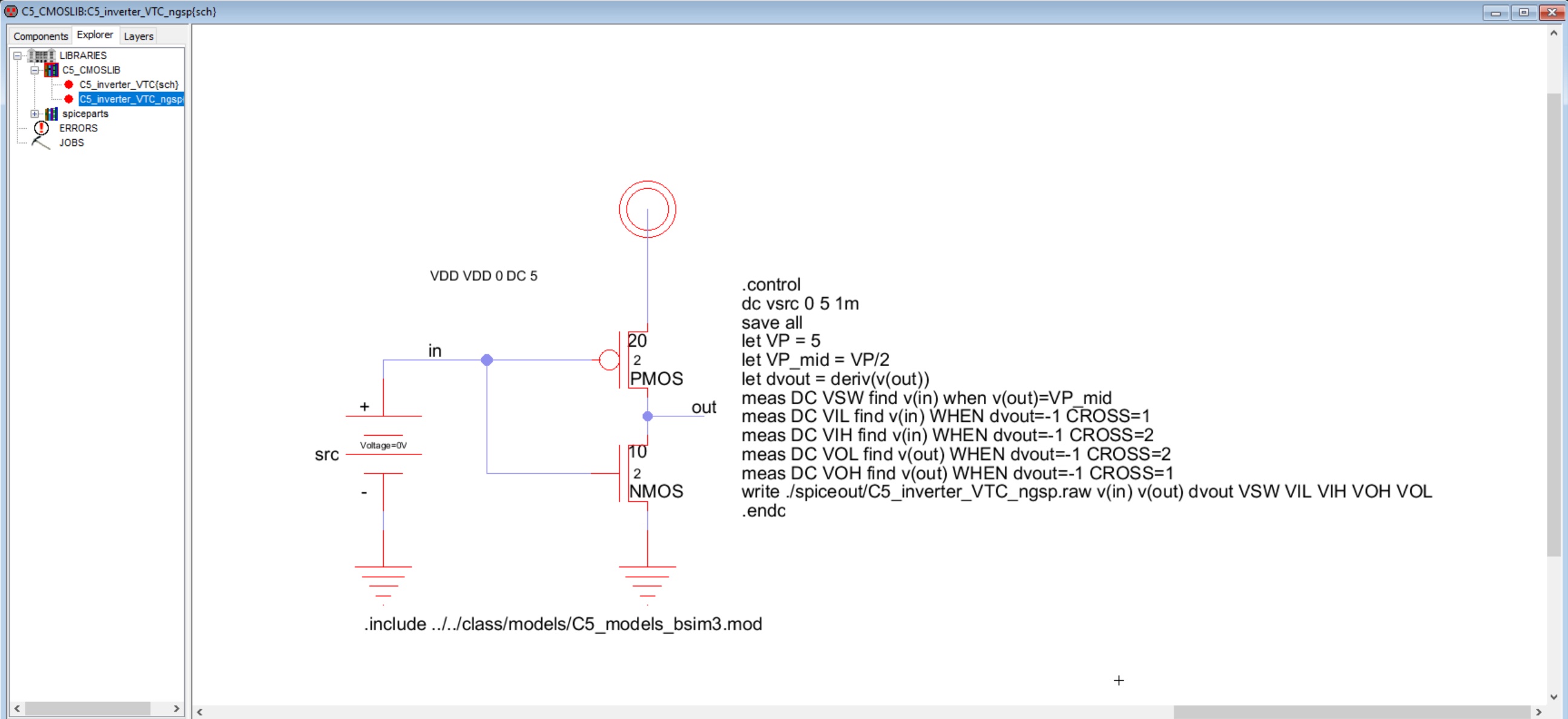 |
don't forget to check the schematic correctness (key binding F5)
run the simulation (key binding Shift S)
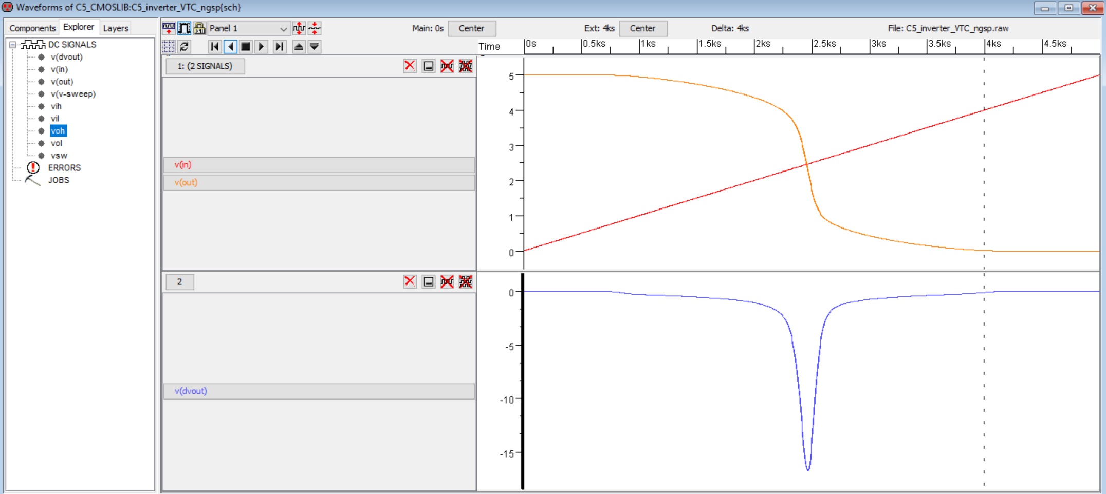
plot the simulation output (key binding Alt S)
NOTE: if a spice input file contains a control section (.control … .endc), when running ngspice in batch mode (-b command line option) the -r rawfile command line option is ignored.
the raw file must be written from within the control section (./spiceout/C5_inverter_VTC_ngsp.raw)
 |
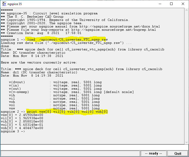
 |
to print the inverter's static parameters (VSW, VOH, VIH, VOL, VIL) we use directly ngspice.
 |