CPEN 230L: Introduction to Digital Logic lab. - S02
Grading
The lowest score will be dropped
| Letter | Percentage |
| A | 100-94 |
| A– | 93-90 |
| B+ | 89-86 |
| B | 85-82 |
| B– | 81-78 |
| C+ | 77-74 |
| C | 73-70 |
| C– | 69-66 |
| D+ | 65-62 |
| D | 61-58 |
| F | 57-0 |
Assignments
The documents for each lab are posted on Blackboard
| Lab no. | Topic | Location |
| 1 | Cedar Software and Logic Trainer | HRK 214 |
| 2 | Basic Gates | HRK 214 |
| 3 | One Gate Type | HRK 214 |
| 4 | Full Adder Design | HRK 214 |
| Verilog Tutorial | HRK 100 | |
| 5 | Quartus Prime, FPGA Programming | HRK 100 |
| 6 | Verilog, ModelSim | HRK 100 |
| 7 | Mux, Decoder, 7-segment Displays | HRK 100 |
| 8 | Numbers and Displays | HRK 100 |
| 9 | Latches, Flip-Flops, Counters | HRK 100 |
| 10 | Switch Debouncing, Counters | HRK 100 |
| 11 | State Machines | HRK 100 |
| 12a | Final Project #1 | HRK 100 |
| 12b | Final Project #2 | HRK 100 |
Free Tools
Cedar Logic Simulator
LogiSim (website)
Icarus Verilog (website)
GTKWave (website and documentation)
Check Icarus installation with this simple example:
//hello.v
module main;
  initial
    begin
      $display("Hello, World");
      $finish ;
    end
endmodule
iverilog -o design hello.v
vvp design
Hello, World
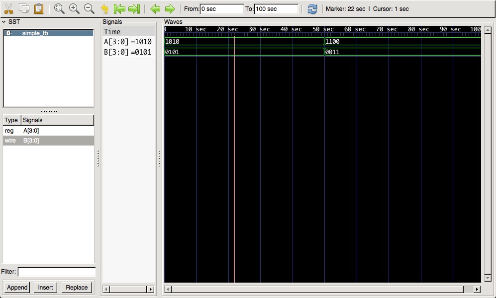
Check GTKWave installation with this simple example:
// simple.v
module simple(A, B);

   input  [3:0] A;
   output [3:0] B;

   // mix up the input bits
   assign B = { A[0], A[1], A[2], A[3] };

endmodule
//simple_tb.v
module simple_tb;

   reg [3:0] A = 4'b1010;

   wire [3:0] B;

   initial
     begin
        $dumpfile("simple.vcd");
        $dumpvars(0);
        $monitor("A is %b, B is %b.", A, B);
        #50 A = 4'b1100;
        #50 $finish;
     end

   simple dut(A, B);

endmodule
iverilog -o design simple.v simple_tb.v
vvp design
gtkwave simple.vcd
VCD info: dumpfile simple.vcd opened for output.
A is 1010, B is 0101.
A is 1100, B is 0011.
 |
Commercial Tools
Quartus Prime (by Altera/Intel)
ModelSim (by Mentor Graphics)
A tutorial on how to use Quartus Prime and Modelsim with Verilog
Altera's original Tutorial (skip section 6 and section 7-2).
instead of section 6 of the original Tutorial please follow section “7: Simulation” of the condensed tutorialA condensed version of the Tutorial
A very terse summary of the Tutorial
RTL code (exor gate):
// File: light.v
// A simple exor gate
module light(x1,x2,f);
input x1,x2;
output f;
assign f= (x1 & ~x2) | (~x1 & x2);
endmodule
Testbench:
// File: light_tb.v
// Test Bench for the light module
// author: Claudio Talarico

`timescale 1ns / 1ns

module light_tb;
// inputs to DUT (RTL Hardware)
reg ain;
reg bin;
//outputs from DUT
wire cout;

// instantiate the DUT
light dut(
.x1( ain ),
.x2( bin ),
.f( cout )
);

// output the simulation in graphical format
initial
begin
  $dumpfile("light.vcd");
  $dumpvars(0);
end

//initialize inputs
initial
begin
  ain = 0;
  bin = 0;
end

// generate ain values
always
begin
# 20 ain = ~ain;
end

// generate bin values
always
begin
# 40 bin = ~bin;
end

// output the simulation in textual format
initial
begin
  $monitor("At time %t, X1 is = %b, X2 is %b, F is %b",
          $time, ain, bin, cout);
end

// stop the simulation from running forever
initial
begin
  # 200 $stop;
end

endmodule
Pins Assignment:
# File: light.csv
# Pin Assignments
To, Direction, Location
x1, input, PIN_AB28
x2, input, PIN_AC28
f, output, PIN_E21
QuickStart on Verilog
A concise document on how to write good quality Verilog for synthesis by Cliff Cummings
One more example of verilog code: an edge detector state machine
RTL code to implement the edge detector hardware:
// Edge Detector - Claudio Talarico
module edgedetector (Clk, Rst, Din, Pulse);
input Clk, Rst, Din;
output Pulse;
reg pulse_d, Pulse;

parameter zero=0, pedge=1, nedge=2, one=3;
reg state, nextstate;

// Combinational logic
always @ (state or Din)
begin

  case (state)
    zero :
      begin
        if (Din == 0)
          begin
            nextstate = zero;
            pulse_d = 0;
          end
        else
          begin
            nextstate = pedge;
            pulse_d = 1;
          end
      end
    one :
      begin
        if (Din)
          begin
            nextstate = one;
            pulse_d = 0;
          end
        else
          begin
            nextstate = nedge;
            pulse_d = 1;
          end
      end
    pedge :
      begin
        if (Din)
          begin
            nextstate = one;
            pulse_d = 0;
          end
        else
          begin
            nextstate = nedge;
            pulse_d = 1;
          end
      end
    nedge :
      begin
        if (Din)
          begin
            nextstate = pedge;
            pulse_d = 1;
          end
        else
          begin
            nextstate = zero;
            pulse_d = 0;
          end
      end
    default :
      begin
        nextstate = zero;
        pulse_d = 0;
      end
  endcase
end

//sequential logic
always @ (posedge Rst or posedge Clk) //active high async. reset
begin
  if (Rst)
    begin
      state <= zero;
      Pulse <= 0;
    end
  else
    begin
      state <= nextstate;
      Pulse <= pulse_d;
    end
end

endmodule
Test vectors (stimuli & expected outputs) read in by testbench:
11
10
10
10
10
01
11
10
10
10
Testbench:
// Edge Detector TestBench - Claudio Talarico

`timescale 1ns/1ns

module edgedetector_tb;
parameter ClkPeriod=20, NVect=10, ClkOffset=2, ProbeDel = 2,  NField = 2;
integer j, fc; //fc=failcount
integer Log_File;
reg [NField : 1] Vmem [1 : NVect];
reg Pulse_exp;
reg Clk_tb;

// inputs to RTL hardware model (Device Under Test)
reg Clk, Rst, Din;

//outputs from DUT
wire Pulse;

//instantiate the DUT
edgedetector edge_detector_inst(Clk, Rst, Din, Pulse);

initial
begin
  $dumpfile("edgedetector.vcd");
  $dumpvars(0);
end

// initialiaze inputs
initial
  begin
    Rst=0;
    Din=0;
    Clk=0;
  end

// initialize testbench
initial
  begin
    Clk_tb = 0;
    fc = 0;
  end

//setup a free running virtual clock
always
  begin
    #(ClkPeriod/2) Clk_tb = ~Clk_tb;
  end

//setup a free running system clock
initial
  begin
    #ClkOffset; //initial offset between the clocks
    forever
      #(ClkPeriod/2) Clk = ~Clk;
  end

// Perform System Reset
initial
  begin
    #2;
    #1 Rst = 1;
    #4 Rst = 0;
  end

// main test
initial
  begin
    Log_File = $fopen("logfile");
    $readmemb("test.vec", Vmem);

    for(j=1;j<=NVect;j=j+1)
    begin
      @ (posedge Clk_tb);
      begin
        {Din,Pulse_exp} = Vmem[j];
        #(ClkOffset + ProbeDel); // let value settle
        if (Pulse !== Pulse_exp)
        begin
          $fdisplay(Log_File, "Time=%t ::", $time," ***** Mismatch on Vector %d *****", j);
          fc = fc + 1;
        end else
        begin
          $fdisplay(Log_File, "Time=%t ::", $time, "vector %d successfull", j);
        end
      end
    end
    if(!fc) $fdisplay(Log_File, "Simulation finished successfully");
    else $fdisplay(Log_File, "***** Simulation finished unsuccessfully *****");
    $fclose(Log_File);
    $finish;
  end

initial
  begin
    $monitor("Time=%t :: ", $time, "Clk_tb=%b, Clk=%b, Din=%b, Pulse=%b", Clk_tb, Clk, Din, Pulse);
  end

endmodule